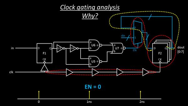
Now here, I am putting an AND gate in capture clock path to register bank, that will open only when one of its input receives a ‘logic 1’ OR when ‘EN’ is high.
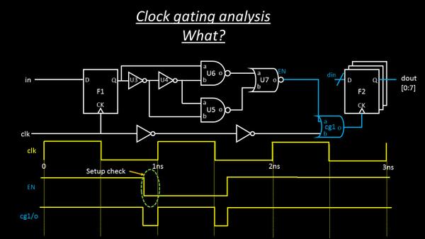
There’s a catch in above ‘EN’ signal. It can’t arrive anywhere in between the logic high or
logic low level of clock signal, but, it needs to meet certain criteria, like if ‘EN’ goes high, it needs to go high before certain time of rising clock edge (resulting to setup-time check) and needs to remain high for the entire clock cycle ‘high’ (resulting in hold time check). This technique of using an ‘AND’ gate is referred to as ‘Active high’ clock gating technique. Can you figure out why? Because a high on ‘EN’ signal allows the clock cycle to hit register bank,
thus allowing new data in to be loaded to data out.
Let’s find out HOW this technique helps: Well, you should have figured out till now. When your ‘EN’ is 0, the AND gate turns off, thus blocking clock to register bank, thereby retaining data out what it is, rather than reloading same data again and again (first image)
So how does ‘Active low’ clock gating looks like?
Hmmmmm….look below image and you will be able to figure out, why below technique is called as ‘Active low’ clock gating