For those who have been in sync with my course on Static timing analysis, will already know this topic very well. For those who haven’t, donot worry. This is the perfect blog for you. And also, this will make you realize how different and exclusive our course on STA is. If you find so, below is the link for (pre)launch
https://www.udemy.com/vlsi-academy-sta-checks/?couponCode=new_course_v8
What we know is, we model jitter as ‘clock uncertainty’. The question (that everyone is keen to know), who decides jitter or uncertainty value. Well, there is physics behind this, and (donot worry) we will not go into much details, but in brief
This is
where an eye diagram is really helpful. Stay with me and I will conclude what an eye diagram is, why is it called an ‘eye’ diagram and how do we get ‘jitter’ values
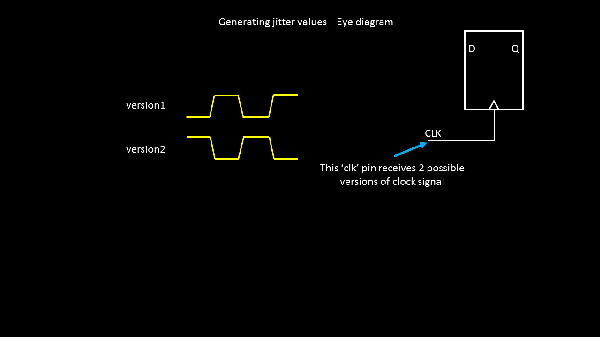
To begin with, look into the below flop clock pin. It expects 2 versions of clock signal (say for eg.) – the real one and the inverted
one: