(Image snapshot from one previous participant GitHub repo - Zakir Hussain)
Hi
The world of Very Large Scale Integration (VLSI) and open-source instruction set architectures, such as RISC-V, presents a unique landscape for burgeoning engineers to explore and
innovate. The image showcased here, provided by a previous participant in our Free RISC-V and VLSI Internship Program—exemplifies the practical learning experiences we offer at VSDSquadron mini.
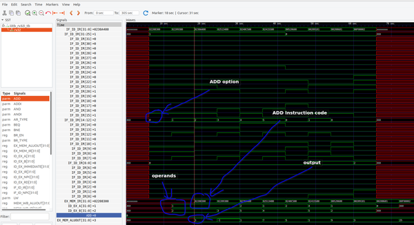
The waveform captured represents a snapshot of a typical debugging session using a VSDSquadron Mini Board. This particular instance
illustrates the internal operations of a RISC-V processor as it executes an "ADD" instruction—a fundamental operation in any processor's instruction set.
Understanding the Image:
Instruction Fetch (IF): The leftmost column of the waveform shows the instruction fetch stage, where the processor retrieves the "ADD" instruction from memory.
This is identified by the binary code “02203040” corresponding to the RISC-V "ADD" opcode.
Instruction Decode (ID): Once fetched, the instruction is decoded. Here, we can see that the ID stage signals are aligned with the instruction opcode to interpret the instruction type and the involved operands.
Execution (EX): The actual arithmetic
operation happens in the EX stage. This is evident from the signal labeled "EX_MEM_ALUOUT," indicating the output from the arithmetic logic unit (ALU) following the execution of the "ADD" command.
Signal Annotations:
- "ADD option" and "ADD Instruction code" annotations clarify the specific parts of the waveform where the instruction and operands are decoded.
- "operands" and "output" annotations denote
the operand values and the result of the execution, respectively.
The red and green colors distinguish between different types of signals—red often denotes control signals, while green indicates data paths or successful execution stages.
Purpose of the Internship:
This internship program is
designed to provide hands-on experience with RISC-V and VLSI design principles. Using the VSDSquadron Mini Boards, interns are not only able to write assembly level code but also delve into the intricate world of hardware design and signal analysis.
Throughout the program, participants engage in:
- Writing and Testing RISC-V Assembly Code: Students learn to write assembly programs that run on actual RISC-V cores, understanding the nuances of
efficient coding.
- Signal Tracing and Debugging: Viewing waveforms like the one shown teaches interns how to trace the flow of data and control signals through the processor, which is crucial for debugging hardware.
- Real Hardware Implementation: Interns get the opportunity to implement their designs and code on physical mini boards, experiencing the transition from theory to practice.
Closing Thoughts:
Above Participants contribution paints a vivid picture of the in-depth learning that takes place in our internship program. For those interested in the intricate dance of 1s and 0s that breathes life into modern electronics, the Free RISC-V and VLSI Internship Program with VSDSquadron Mini Boards offers an invaluable experience, equipping the next generation of engineers with the skills
required to innovate and excel in the field of computer architecture and VLSI design.
Register using below link:
https://www.vlsisystemdesign.com/vsdsquadronmini/