(Credit: https://circuitdigest.com/tutorial/asynchronous-counter)
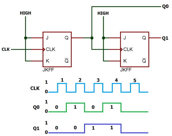
This block counts 0, 1, 2, and 3 repeatedly. The JK Flip Flop with both inputs as HIGH results in toggling of the output as the circuit gets triggered.
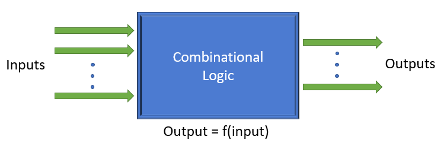
Verilog is one of the many available HDLs used for modelling such circuits. Verilog makes logic blocks that implement one functionality as a module. The inputs and output from the logic design are named ports. The syntax for creating a module is as shown
module <module-name> (<module-port-list>);
//functionality description
endmodule
Design simulators are tools used to verify the intended functionality of the logic block. There are several design simulators both commercial and open-source available for simulating the Verilog designs. For example, Verilator, and Icarus Verilog are the open-source tools used to simulate
the logic.
Typically, the design was verified using test benches written again in Verilog. The test benches call to instantiate the design module and provide necessary test inputs exercising the module. The output signals are observed to see the values given by the design. The output is then compared
to the reference model which gives the expected output. The comparison explains whether the design is performing as expected.
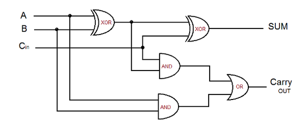
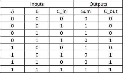
A sample Verilog code that implements full adder is as follows
module full_adder(
input a, b, c_in,
output sum, c_out
);
assign sum = a ^ b ^ c_in;
assign c_out = (a & b) + (b & c_in) + (c_in & a);
endmodule
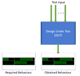
Verification of circuit design takes place by comparing the desired result with passing the test input to the device under test